| H. E. Smith | Spring 2000 |

| Physics 1B - Tutorial #8 |

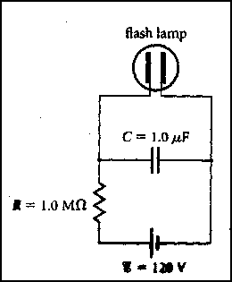
The figure at the right represents the circuit of an emergency highway
flasher. The flash lamp itself has a very high resistance (~107
 ) at voltages below 110V. At voltages
greater than 110V, gas inside the flasher becomes ionized and conducts
electricity; the resistance is then 10 ) at voltages below 110V. At voltages
greater than 110V, gas inside the flasher becomes ionized and conducts
electricity; the resistance is then 10 .
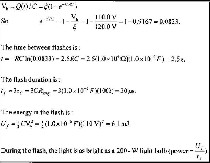
Explain how the flasher works. What determines the time between flashes?
How long is it? What is the duration of the flash? .
Explain how the flasher works. What determines the time between flashes?
How long is it? What is the duration of the flash? Until the capacitor voltage reaches 110V, the high resistance of the flash lamp ensures that it draws no current; the capacitor charges like the RC circuit example in class. When the capacitor voltage reaches 110V, the flasher resistance becomes small compared with that of the resistor and the capacitor discharges through the lamp. |
 |
 |
 /Bq = 5.6 x 10⁻⁸m.
 "
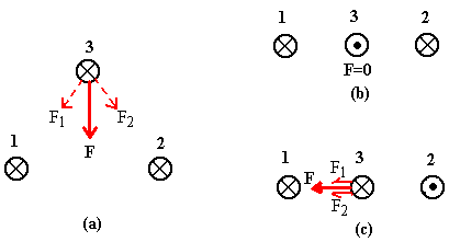
indicating current directed into the page and
"
"
indicating current directed into the page and
" " indicating current out of the page.
Find the direction of the net force on Wire 3 in each case. In figure (c)
the distance between nearby wires is 10cm and the current is 1A in each wire.
Calculate the force on Wire 3.

Problem 4
 r) = 4 x 10⁻⁶ N


![]() Physics 1B Home
Physics 1B Home
![]() Tutorials
Tutorials
![]() Tutorial #7
Tutorial #7
![]() Tutorial #9
Tutorial #9